 |
| 総重量 |
MPU6050 6軸モーションセンサからMadgwickFilter・PID制御に加えてVL53レーザー測距センサモジュールによる浮上制御とジョイスティックによる左右回転・上下浮上調整を追加しました。
※2025年~無料RemoteXYは5変数以内に変更になり6変数以上は10秒しか使用できません。
●同ブログ関連記事:【ドローン製作⑫ ESP8266 MPU6050 VL53 テスト】
動画
ドローンの回転
ジョイスティックを右にすると、M2 M4 モータの回転が速くなり、真上から見てドローンが右回転する。(動画)
※プログラムでMadgwickFilterのYAWは使っていない。
YAW = 0 * YAW;(YAWは常にゼロ)
回路図
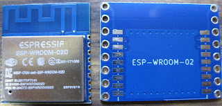
ESP-WROOM-02D+ピッチ変換基板
●Wi-Fiモジュール ESP-WROOM-02D 技適製品 (秋月電子通商)
●ESP-WROOM-02 ピッチ変換基板 コンパクト(アマゾン)
同ブログ関連記事:【ドローン製作③ ESP8266コントローラ 組立】
ESP8266配線
落下衝撃で端子が変形した際、端子にハンダしたチップ抵抗10kΩが割れたので金属皮膜抵抗に3個入れ替えました。
ESP8266+MPU6050
落下の衝撃により端子が変形しています。
ドローン用LIPO バッテリー3.7V(250mA)
満充電(4.2V)を直接ESP8266に接続してテストを行っています。
ESP8266規格を超えて使用
・電源電圧min.:2.7V
・電源電圧max.:3.6V
VL53
同ブログ関連記事:【ドローン製作⑪ ESP8266 MPU6050 VL53 テスト】
プログラム書込み
パソコンUSBポートのFT232RL USBシリアル変換とESP8266のTXD・RXD・VCC・GND接続して、プログラム書込みを行います。
●FT232RL
ショートピン➨3.3V側
●ESP8266
IO0とGNDにショートピン挿入(書込み)
RemoteXYアプリ
●同ブログ関連記事:【RemoteXY使い方】
【Properties】【Configuration】設定変更
[Connection]WiFi access point
[Board]ESP8266 based board
[Module]WiFi on chip
【Apply】実行
【Slider】をスマホ画面に貼付け、大きさ・色等を変更
(コントロール配置は5個以内)
【Get source code】実行
コードをArduino IDE エディタ画面に貼付てスケッチを行う。
ジョイスティック :左右回転・上下浮上コントロール
ON:自動浮上
スライダー01:kp
スライダー02:ki x 0.01
スライダー03:浮上高
おおよそKp:40 Ki:0.1 (Kd=10)
Arduino IDE
プログラム
//////////////////////////////////////////////
// RemoteXY include library //
//////////////////////////////////////////////
// you can enable debug logging to Serial at 115200
//#define REMOTEXY__DEBUGLOG
// RemoteXY select connection mode and include library
#define REMOTEXY_MODE__WIFI_POINT
#include <ESP8266WiFi.h>
// RemoteXY connection settings
#define REMOTEXY_WIFI_SSID "RemoteXY"
#define REMOTEXY_WIFI_PASSWORD "12345678"
#define REMOTEXY_SERVER_PORT 6377
#include <RemoteXY.h>
// RemoteXY GUI configuration
#pragma pack(push, 1)
uint8_t RemoteXY_CONF[] = // 69 bytes
{ 255,6,0,0,0,62,0,17,0,0,0,81,1,106,200,1,1,5,0,4,
8,139,94,16,128,191,26,4,8,159,94,16,128,190,26,4,8,179,94,16,
128,190,26,10,71,108,29,29,49,4,26,31,79,78,0,31,79,70,70,0,
5,1,4,104,104,0,2,26,31 };
// this structure defines all the variables and events of your control interface
struct {
// input variables
int8_t slider_01; // from 0 to 100
int8_t slider_02; // from 0 to 100
int8_t slider_03; // from 0 to 100
uint8_t pushSwitch_01; // =1 if state is ON, else =0
int8_t joystick_01_x; // from -100 to 100
int8_t joystick_01_y; // from -100 to 100
// other variable
uint8_t connect_flag; // =1 if wire connected, else =0
} RemoteXY;
#pragma pack(pop)
/////////////////////////////////////////////
// END RemoteXY include //
/////////////////////////////////////////////
#include "MPU6050.h"
MPU6050 accelgyro;
#include <MadgwickAHRS.h>
Madgwick MadgwickFilter;
#include <VL53L0X.h>
VL53L0X gVL530X;
int16_t ax, ay, az;//加速度 int16_tは2バイトの符号付き整数
int16_t gx, gy, gz;//角速度 同上
float ROLL, PITCH, YAW;
float ROLL_P, ROLL_I, ROLL_D, ROLL_M;
float PITCH_P, PITCH_I, PITCH_D, PITCH_M;
float R, P, Y;
float Kp, Kd, Ki;
int dist;
int throttle;
int S1, S2, S3, Jx, Jy, Auto;
#define M1 12
#define M2 13
#define M3 14
#define M4 15
#define PWN_FREQ 1000 // PWM frequency: 1000Hz(1kHz)
#define PWN_RANGE 100 // PWN range: 100
void setup()
{
RemoteXY_Init ();
pinMode(M1, OUTPUT);
pinMode(M2, OUTPUT);
pinMode(M3, OUTPUT);
pinMode(M4, OUTPUT);
Wire.begin();
Serial.begin(115200);
accelgyro.initialize();//I2Cデバイスの初期化
delay(300);
MadgwickFilter.begin(100);//フィルタのサンプリングを100Hzで
analogWriteFreq(PWN_FREQ);
analogWriteRange(PWN_RANGE);
gVL530X.init();
gVL530X.setTimeout(500);
gVL530X.startContinuous(); //連続
}
void loop()
{
RemoteXY_Handler ();
S1 = RemoteXY.slider_01; //kp
S2 = RemoteXY.slider_02; //ki
S3 = RemoteXY.slider_03; //浮上高
Jx = RemoteXY.joystick_01_x; //左右回転
Jy = RemoteXY.joystick_01_y; //上下浮上
Auto = RemoteXY.pushSwitch_01; //自動浮上
//自動浮上
if(Auto == 1 ){
if(dist < S3*10 ){ //スライダ(浮上高)
throttle = throttle+10;
throttle = min(throttle,70); //スロットル上限制限
}else{
throttle = throttle-5;
throttle = max(throttle,50); //スロットル下限制限
}
}else{
throttle = 0;
ROLL_M = 0;
PITCH_M = 0;
Jx = 0;
Jy = 0;
}
dist = gVL530X.readRangeContinuousMillimeters();
accelgyro.getMotion6(&ax, &ay, &az, &gx, &gy, &gz);
MadgwickFilter.updateIMU(gx / 131.0, gy / 131.0, gz / 131.0, ax / 16384.0, ay / 16384.0, az / 16384.0);
ROLL = MadgwickFilter.getRoll();
PITCH = MadgwickFilter.getPitch();
YAW = MadgwickFilter.getYaw();
YAW = YAW - 180;
YAW = 0 * YAW;
// 角速度値を分解能で割って角速度に変換する
float dpsX = gx / 131.0;
float dpsY = gy / 131.0;
float dpsZ = gz / 131.0;
//定数
Kp = S1;
Ki = S2 * 0.01;
Kd = 10;
// PID制御
ROLL_P = ROLL / 90; // P成分:傾き-90~90度 → -1~1
ROLL_I += ROLL_P; // I成分:傾きの積算。
if (10 < abs(ROLL_I)) ROLL_I = 0; //上限設定
ROLL_D = dpsX / 250; // D成分:角速度-250~250dps → -1~1
ROLL_M = ROLL_P * Kp +
ROLL_I * Ki +
ROLL_D * Kd;
PITCH_P = PITCH / 90; // P成分:傾き-90~90度 → -1~1
PITCH_I += PITCH_P; // I成分:傾きの積算。
if (10 < abs(PITCH_I)) PITCH_I = 0; //上限設定
PITCH_D = dpsY / 250; // D成分:角速度-250~250dps → -1~1
PITCH_M = PITCH_P * Kp +
PITCH_I * Ki +
PITCH_D * Kd;
//シリアルモニタ
//Serial.print("ROLL");Serial.print(ROLL); Serial.print("| ");
//Serial.print("PITCH");Serial.print(PITCH); Serial.print("| ");
//Serial.print("dist");Serial.print(dist); Serial.print("| ");
//Serial.print("\n");
//シリアルプロッタ
//Serial.print(ROLL_M);Serial.print(",");
//Serial.print(PITCH_M);
//Serial.print("\n");
analogWrite(M1, (throttle + Jy/10 + ROLL_M + PITCH_M - YAW));
analogWrite(M2, (throttle + Jy/10 + Jx/10 + ROLL_M - PITCH_M + YAW));
analogWrite(M3, (throttle + Jy/10 - ROLL_M - PITCH_M - YAW));
analogWrite(M4, (throttle + Jy/10 + Jx/10 - ROLL_M + PITCH_M + YAW));
delay(5);
}


.png)
.png)


0 件のコメント:
コメントを投稿