 |
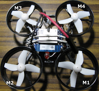
RemoteXY操作を変更し、モータ4個を同時にスロットル操作して浮上を試みましたが真上に浮上しません。次回、MadgwickFilterによる姿勢制御をテストします。
■緑スライダー
M1~M4同時操作(スロットル)
青スライダー
■ M1.M2.M3.M4個別操作(微調整)
●同ブログ関連記事:【ドローン 製作③ ESP8266コントローラ 組立】
動画
回路図
ESP8266コントローラ
ドローン用LIPO バッテリー3.7V(250mA)満充電(4.2V)を直接ESP8266接続して使用しました。
ESP8266規格を超える使用
・電源電圧min.:2.7V
・電源電圧max.:3.6V
アマゾン
RemoteXYアプリ
●同ブログ関連記事:【RemoteXY使い方】
【Properties】【Configuration】設定変更
[Connection]WiFi access point
[Board]ESP8266 based board
[Module]WiFi on chip
【Apply】実行
【Slider】をスマホ画面に貼付、大きさ・色等を変更
(コントロール配置は5個以内)
【Get source code】実行
コードをArduino IDE エディタ画面に貼付てスケッチを行う。
Arduino IDE
プログラム
// RemoteXY select connection mode and include library
#define REMOTEXY_MODE__ESP8266WIFI_LIB_POINT
#include <ESP8266WiFi.h>
#include <RemoteXY.h>
// RemoteXY connection settings
#define REMOTEXY_WIFI_SSID "RemoteXY"
#define REMOTEXY_WIFI_PASSWORD "12345678"
#define REMOTEXY_SERVER_PORT 6377
// RemoteXY configurate
#pragma pack(push, 1)
uint8_t RemoteXY_CONF[] = // 50 bytes
{ 255,5,0,0,0,43,0,16,195,1,4,128,1,56,61,10,204,26,4,128,
1,67,61,10,204,26,4,128,1,78,61,10,204,26,4,128,1,89,61,10,
204,26,4,0,50,254,9,57,134,26 };
// this structure defines all the variables and events of your control interface
struct {
// input variables
int8_t slider_1; // =0..100 slider position
int8_t slider_2; // =0..100 slider position
int8_t slider_3; // =0..100 slider position
int8_t slider_4; // =0..100 slider position
int8_t slider_5; // =0..100 slider position
// other variable
uint8_t connect_flag; // =1 if wire connected, else =0
} RemoteXY;
#pragma pack(pop)
/////////////////////////////////////////////
// END RemoteXY include //
/////////////////////////////////////////////
#define M1 12
#define M2 13
#define M3 14
#define M4 15
#define PWN_FREQ 1000 // PWM frequency: 1000Hz(1kHz)
#define PWN_RANGE 100 // PWN range: 100
void setup()
{
RemoteXY_Init ();
pinMode(M1,OUTPUT);
pinMode(M2,OUTPUT);
pinMode(M3,OUTPUT);
pinMode(M4,OUTPUT);
analogWriteFreq(PWN_FREQ);
analogWriteRange(PWN_RANGE);
}
void loop()
{
RemoteXY_Handler ();
delay(100);
int S1 = RemoteXY.slider_1;
int S2 = RemoteXY.slider_2;
int S3 = RemoteXY.slider_3;
int S4 = RemoteXY.slider_4;
int S5 = RemoteXY.slider_5;
analogWrite(M1, (S5*0.9+S1*0.1));
analogWrite(M2, (S5*0.9+S2*0.1));
analogWrite(M3, (S5*0.9+S3*0.1));
analogWrite(M4, (S5*0.9+S4*0.1));
}


.png)
.png)


0 件のコメント:
コメントを投稿